Showing posts with label SOLID MODELING. Show all posts

Thursday, 31 May 2012

Routing Systems


Routing Systems: General
Measure Distance
A Distance measurement with Type of Points on Curves or Routing Path Length gives you distance between points on a set of curves or the length of a routing path.
USE:
Use Measure Distance to get the information about the length of a path.
Menu      Analysis→Measure Distance
Toolbar  Utility


Minimum bend radius spline violations

A new design rule capability highlights specific violation locations for splines
violating the minimum curve bend radius design rule.
USE:

Use this new capability to find the exact location of sharp corners on splines
to help edit or eliminate the problem.
Application Routing Electrical / Routing Mechanical
Menu

Analysis→Check Mate→Run Tests , and
Analysis→Design Rules→Interactive Check
For automatic checks:
Application Routing Electrical
Menu Preferences→Wiring
Location in dialog box General page-->Report Routing Errors check box.


Smart Router: Quick Path

Quick Path automatically creates a collision free path between two specified
locations, and optionally, through specified intermediate locations. The
resulting path comprises lines and arcs, but not splines, and avoids obstacles
by a specified clearance value. You can adjust the path for the final desired
path.
USE:

Use Quick Path to avoid manually creating a collision-free non-trivial path
between two locations.

Application Routing Electrical / Routing Mechanical
Menu Insert→Routing Path→Quick Path
Toolbar Routing Path→Quick Path


Tuesday, 29 May 2012

Block, Cylinder, Sphere, and Cone associativity


The Block, Cylinder, Sphere, and Cone commands are now associative to their respective point, vector, and curve positioning objects.
If you subsequently move one of the positioning objects, the feature updates associatively.


Why should I use it?
This new associativity makes primitive features more useful for modeling prismatic objects such as machining fixtures.


Where do I find it?
Application Modeling
Menu Insert-->Design Feature-->Block/Cylinder/Sphere/Cone

Tuesday, 15 May 2012

WAVE General Relinker


The General Relinker dialog box now has the following enhancements and
changes:
• You can specify whether suppressed components should be included
as source objects by selecting or clearing the Include Suppressed
Components check box in the Settings group.
• You can define the source searching scope for the relinking operation by
setting the new Source Scope option (in the Relink group) to either Parts
in Assembly or Parts in Session.
• You can control whether the General Relinker looks for non-broken WAVE
links, as well as broken ones, with the new Include Non-broken WAVE
Links check box. When this check box is not selected, update performance
is faster, and non-broken links that share the same naming convention as
broken links are not reparented.
• Relink Scope (in the Relink group) is now Target Scope.
• Face/Curve Direction Adjustment, in the Settings group, is now called
Face Normal/Curve Direction Adjustment.

Geometry selection for designing in an assembly context


You can now easily select geometry outside the work part for many NX
Modeling commands. You can automatically copy geometry you select outside
the work part into the work part as either WAVE geometry (which updates
when the source geometry changes) or non-associative geometry (which does
not update).


This functionality uses two new options on the Selection bar: (1) Select
Scope and (2) Create Interpart Link.
You can control interpart selection with the Select Scope option to select
geometry from assembly components other than the work part.
Select Scope options are:
• Entire Assembly
Use this option to select geometry from any component in the assembly.
• Within Work Part and Components
Use this option to limit the selection of geometry to the current work part
and its components, if it is a subassembly.
• Within Work Part Only
Use this option to limit the selection of geometry to the current work part.
If the Select Scope option is not available for a command, this indicates that
the command does not support this design in context functionality. In this
case, you can still use one of the other traditional methods to create interpart
links, such as Wave Geometry Linker.
When selecting geometry from a component other than the work part, you
may choose to create an interpart link or to use the geometry unassociatively.
To create an interpart link, turn on the Create Interpart Link option before
making a selection. For commands where you make multiple selections, you
can turn this option on or off independently for each selection.

Sunday, 29 April 2012

Radial Engine Assembly


In this exercise you will create the Radial Engine assembly shown in below Figure.


 The Radial Engine assembly will be created in two parts, one will be the sub assembly and the other will be the main assembly. The dimensions of the components of the Radial Engine assembly are shown in below  Figures 


Thursday, 19 April 2012

Synchronous modeling: Move Face

Move face is an option to move the faces of the particular component to certain limit as per the requirement.
Basically this option is useful when you have parametric models and just to show 3 models to somebody like 3rd party without editing the main features of the component.
The above image shows how to open Synchronous modeling.
Let us explore the first option in this tool
MOVE FACE:
>Select the face which you want to move.
>You have so many options to move the face like
Distance,
Angle,
Point to Point etc.

>You can choose any one option as per the convenience .
(Here I shown with distance)

You  can see an option called FACE FINDER in the above tool .
There are three options in that.
Results,Settings,Reference.

in Settings,You can set the options as per requirement.

Reference is the option to call the component to particular location.

Wednesday, 18 April 2012

Assembly Load Option


To define how and where NX load part file, we need to configure some basic function like, save, open and assembly.
Dialog box will appear, like the below picture, from the dialog box here we can set up load the file first time as may be required, it is easier for us in working with Unigraphic later.


 1. Part version
You can set whether each time to load a new file or open a file starting from the folder, or history. UGS default is the folder.
2. scope
You can choose all the components directly on the load time, or just based on the stored data, or other options, are generally used are all components (including part assembly).
3.Reference Sets
You can call the components as per the reference set created while modeling.


4. Save Load option
Save to file, serve to redirect the folder to load the first time, after the set, every time you open a new file, the folder will be automatically redirected to it.
So is the open from the file, after we set the folder, each time it opens the file it will automatically be redirected to a folder that was set.

Sunday, 1 April 2012

Offset Face

Go to Insert-->offset/Scale-->Offset Face


Its a simple command for extending the faces of particular component without going and modifying the sketch.
A face of the block is extended upto 10mm using offset Face command

Saturday, 31 March 2012

Offset Surface

Go to Insert-->offset/scale-->Offset Surface
In the offset surface command 
in feature bar you can see OUTPUT
You have two options in this,
1.One feature for connected faces 
This option is useful when you have to create the envelope for the particular component as the tolerance purpose.In this all the faces offset with the connectivity.


2.One feature for each face.
You wont see any connectivity in this command.Each face can be offset individually without any connectivity.

Shell Command

Initially create rectangle either through creating a block command or through sketch.
Then open the shell command from
insert-->offset scale-->shell as shown in below
there are two options in the shell command,
1.Remove faces,then shell
This option is useful when you want to remove the inner material and create a thickness for the out wall as shown in below image
the thickness can be variable with the face,
different faces can select for different thickness


2.Shell all the faces.
In this option out body remains same but inner material removed as shown in below image.


By applying this we cant find the shell applied or not but if you see the section for the block you will find the thickness to the walls.

after section only shell can be visible

Saturday, 25 February 2012

Difference between Chamfer and Blend


1.Blend:
Blend operations add or subtract material to round (fillet) edges.
• Uni graphics provides 3 kinds of blends:
Edge Blend
• Is the only type of blend you need to know how to perform for this class.
• Can be constant or variable radius.
• Good practice rule:
Face Blends
• In face blends you choose two faces instead of an edge.
• Face Blends will trim faces if required.
Soft Blends
• Soft blends are used for styled “Class A” surfaces.
• The curvature varies smoothly


2.Chamfers
• Chamfer add or remove material to create beveled edges.
• The same rules apply to creating chamfers as to creating edge blends.
• Options include:
– Single offset
– Double offset
– Offset and Angle

Wednesday, 11 January 2012

FORM FEATURES -2


Reference Features
These let you create reference planes or reference axes. These references can assist you in creating features on cylinders, cones, spheres and revolved solid bodies.
ô€‚¾ Click on INSERT → DATUM/POINT to view the different Reference Feature options:
Datum Plane, Datum Axis, Datum CSYS, and Point 


Swept Features
These let you create bodies by extruding or revolving sketch geometry. Swept Features include:
• Extruded Body
• Revolved Body
• Sweep along Guide
• Tube
• Styled Sweep


To select a swept feature you can do the following:
ô€‚¾ Click on INSERT → DESIGN FEATURE for Extrude and Revolve
or
ô€‚¾ Click on INSERT → SWEEP for the rest of the options


Remove Features
Remove Features let you create bodies by removing solid part from other parts.
ô€‚¾ Click on INSERT → DESIGN FEATURE
Remove Features include,
• Hole
• Boss
• Pocket
• Pad
• Slot
• Groove


You can also select the features by clicking on the icons


User-Defined features
These allow you to create your own form features to automate commonly used design elements.
You can use user-defined features to extend the range and power of the built-in form features.
ô€‚¾ Click on INSERT → DESIGN FEATURE → USER DEFINED


Extract Features
These features let you create bodies by extracting curves, faces and regions. These features are widely spaced under Associative Copy and Offset/Scale menus. 


Extract Features include:
• Extract
• Sheet from curves
• Bounded plane
• Thicken Sheet
• Sheet to Solid Assistant
 Click on INSERT → ASSOCIATIVE
COPY → EXTRACT for Extract options
ô€‚¾ Click on INSERT → OFFSET/SCALE for
Thicken Sheet and Sheets to Solid Assistant
ô€‚¾ Click on INSERT → SURFACE for
Bounded Plane and Sheet from curves

Tuesday, 10 January 2012

FORM FEATURES


Features are objects that are associatively defined by one or more parents and that retain within the model the order of its creation and modification, thus capturing its history. Parents can be geometrical objects or numerical variables. Features include primitive, surface and solid objects,and certain wire frame objects (such as curves and associative trim and bridge curves). For example, some common features include blocks, cylinders, cones, spheres, extruded bodies, and revolved bodies.


TYPES OF FEATURES

There are six types of Form features: Reference features, Swept features, Remove features, User defined features, Extract features and Primitives.


Click INSERT on the Menu bar As you can see, the marked menus in the figure on the right side contain the commands of Form Features.


The Form Feature icons are grouped in the Form Features Toolbar as shown below. You can choose the icons that you use frequently.


􀂾 Click on the drop down arrow in Form Feature Toolbar
􀂾 Choose ADD OR REMOVE BUTTONS
􀂾 Choose FORM FEATURE


Wednesday, 14 December 2011

Model a Hexagonal Nut


􀂾 Create a new file and save it as Impeller_hexa-nut
􀂾 Click the polygon icon from the toolbar


􀂾 Create a hexagon with each side measuring 0.28685 inches and constructed at the origin
􀂾 Extrude the hexagon by 0.125 inches
The figure of the model is shown below.


ô€‚¾ Choose INSERT → DESIGN FEATURE → SPHERE
􀂾 Choose CENTER, DIAMETER

􀂾 Enter the diameter value 0.57 inches
􀂾 Enter the Point Constructor values as follows

Axes            XC      YC           ZC
Dimension   0.0      0.0       0.125

􀂾 In the Boolean operations dialog box select INTERSECT
The model will look like the following.


We will now use a Mirror command.
ô€‚¾ Choose EDIT → TRANSFORM
􀂾 Select the model and click OK
􀂾 Click MIRROR THROUGH A PLANE
ô€‚¾ Click on the flat side of the model as shown. Be careful not to select any edges
Click on OK

􀂾 Click on COPY
􀂾 Click CANCEL


You will get the following model.
ô€‚¾ Choose INSERT → COMBINE BODIES → UNITE
􀂾 Select the two halves and Unite them
􀂾 Insert a cylinder with the vector pointing in the Z-direction
and with the following dimensions.
Diameter = 0.25 inches
Height = 1 inch
􀂾 Center the cylinder on the origin and subtract this cylinder
from the hexagon nut
Now, we will chamfer the inside edges of the nut.
ô€‚¾ Choose INSERT → DETAIL FEATURE → CHAMFER

􀂾 Select the two inner edges as shown and click OK
􀂾 Enter the Chamfer Offset Diameter as 0.0436 inches and click OK
You will see the chamfer on the nut. Save the model.


Saturday, 3 December 2011

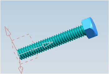
Threading of a hexagonal bolt


Open the model with Hexagonal nut from my previous post:


http://unigraphicsbasicsnmaterial.blogspot.com/2011/12/model-hexagonal-screw.html

  • Choose INSERT → DESIGN FEATURE →THREAD
Here you will see the threading dialog box as shown below.


There are two main options in Threading: 
1)Symbolic and 2) Detailed.

  • Click on the DETAILED radio button
  • Keep the thread as RIGHT HANDED
  • Click on the bolt shaft, the long cylinder below


the hexagon head Once the shaft is selected, all the values will be displayed in the Thread dialog box. Keep all these default values.

  • Click OK

The hexagon bolt should now look like the following. Save the model.


Model a Hexagonal Screw


Create a new file and save it as Impeller_hexa-bolt

  • Choose INSERT → DESIGN FEATURE → CYLINDER
  • The cylinder should be pointing in the Z-direction with the center set at the origin and with the following dimensions:


Diameter = 0.25 inches
Height = 1.5 inches


Now create a small step cylinder on top of the existing cylinder.

  • The dimensions of this cylinder are,

Diameter = 0.387 inches
Height = 0.0156 inches 


  • On the Point Constructor window,click the Center icon at the top
  • Click on the top face of the existing

cylinder as shown in the following figure


Under the Boolean drop-down menu,
choose UNITE


The two cylinders should look like the figure shown below.


Save the model.
Next, we will create a hexagon for the head of the bolt.


  • Choose the icon from the Curves Toolbar as shown


  • On the Polygon window, type 6 for the number of sides


  • Click OK


There are three ways to draw the polygon.
• Inscribed Radius
• Side of Polygon
• Circumscribed Radius

  • Choose SIDE OF POLYGON


On the next window, enter the following dimensions.
Side = 0.246 inches
Orientation Angle = 0.00 degree

  • Click OK
  • On the Point Constructor window, again choose the Center icon
  • Click on the top face of the last cylinder drawn 

The polygon will be seen as shown below. 
If the model is not in wireframe, click on the Wireframe icon in the View Toolbar


Now we will extrude this polygon.

  • Choose INSERT → DESIGN FEATURE → EXTRUDE
  • Click on all six lines of the hexagon to choose the surface that is required to be extruded
  • Enter the End Distance as 0.1876 inches

The model looks like the following after extrusion


On top of the cylinder that has a diameter of 0.387 inches, insert another cylinder with the following dimensions.


Diameter = 0.387 inches
Height = 0.1875 inches


You will only be able to see this cylinder when the model is in wireframe since the cylinder is inside the hexagon head. The model will look like the following.


We will now use the feature operation Intersect.

  • Choose INSERT → DESIGN FEATURE → SPHERE
  • Choose DIAMETER, CENTER


  • Enter the value of the diameter as 0.55 inches and click OK
  • On the Point Constructor window, choose the Center icon
  • Select the bottom of the last cylinder drawn, which is inside the hexagon head and has a diameter of 0.387 inches and a height of 0.1875 inches as shown below

Click OK


This will give take you the next Dialog box which will ask you to choose the Boolean operation to be performed.


  • Choose INTERSECT


It will ask you to select the target solid


  • Choose the hexagonal head as shown 


  • Click CANCEL


This will give you the hexagonal bolt as shown below.


Check here how to add threading to the above bolt in the next post:


http://unigraphicsbasicsnmaterial.blogspot.com/2011/12/threading-of-hexagonal-bolt.html

Related Posts Plugin for WordPress, Blogger...