Showing posts with label Tips n Tricks for UG. Show all posts

Tuesday, 15 May 2012

WAVE General Relinker


The General Relinker dialog box now has the following enhancements and
changes:
• You can specify whether suppressed components should be included
as source objects by selecting or clearing the Include Suppressed
Components check box in the Settings group.
• You can define the source searching scope for the relinking operation by
setting the new Source Scope option (in the Relink group) to either Parts
in Assembly or Parts in Session.
• You can control whether the General Relinker looks for non-broken WAVE
links, as well as broken ones, with the new Include Non-broken WAVE
Links check box. When this check box is not selected, update performance
is faster, and non-broken links that share the same naming convention as
broken links are not reparented.
• Relink Scope (in the Relink group) is now Target Scope.
• Face/Curve Direction Adjustment, in the Settings group, is now called
Face Normal/Curve Direction Adjustment.

Sunday, 29 April 2012

Radial Engine Assembly


In this exercise you will create the Radial Engine assembly shown in below Figure.


 The Radial Engine assembly will be created in two parts, one will be the sub assembly and the other will be the main assembly. The dimensions of the components of the Radial Engine assembly are shown in below  Figures 


Wednesday, 14 December 2011

Model a Hexagonal Nut


􀂾 Create a new file and save it as Impeller_hexa-nut
􀂾 Click the polygon icon from the toolbar


􀂾 Create a hexagon with each side measuring 0.28685 inches and constructed at the origin
􀂾 Extrude the hexagon by 0.125 inches
The figure of the model is shown below.


􀂾 Choose INSERT → DESIGN FEATURE → SPHERE
􀂾 Choose CENTER, DIAMETER

􀂾 Enter the diameter value 0.57 inches
􀂾 Enter the Point Constructor values as follows

Axes            XC      YC           ZC
Dimension   0.0      0.0       0.125

􀂾 In the Boolean operations dialog box select INTERSECT
The model will look like the following.


We will now use a Mirror command.
􀂾 Choose EDIT → TRANSFORM
􀂾 Select the model and click OK
􀂾 Click MIRROR THROUGH A PLANE
􀂾 Click on the flat side of the model as shown. Be careful not to select any edges
Click on OK

􀂾 Click on COPY
􀂾 Click CANCEL


You will get the following model.
􀂾 Choose INSERT → COMBINE BODIES → UNITE
􀂾 Select the two halves and Unite them
􀂾 Insert a cylinder with the vector pointing in the Z-direction
and with the following dimensions.
Diameter = 0.25 inches
Height = 1 inch
􀂾 Center the cylinder on the origin and subtract this cylinder
from the hexagon nut
Now, we will chamfer the inside edges of the nut.
􀂾 Choose INSERT → DETAIL FEATURE → CHAMFER

􀂾 Select the two inner edges as shown and click OK
􀂾 Enter the Chamfer Offset Diameter as 0.0436 inches and click OK
You will see the chamfer on the nut. Save the model.


Saturday, 3 December 2011

Threading of a hexagonal bolt


Open the model with Hexagonal nut from my previous post:


http://unigraphicsbasicsnmaterial.blogspot.com/2011/12/model-hexagonal-screw.html

  • Choose INSERT → DESIGN FEATURE →THREAD
Here you will see the threading dialog box as shown below.


There are two main options in Threading: 
1)Symbolic and 2) Detailed.

  • Click on the DETAILED radio button
  • Keep the thread as RIGHT HANDED
  • Click on the bolt shaft, the long cylinder below


the hexagon head Once the shaft is selected, all the values will be displayed in the Thread dialog box. Keep all these default values.

  • Click OK

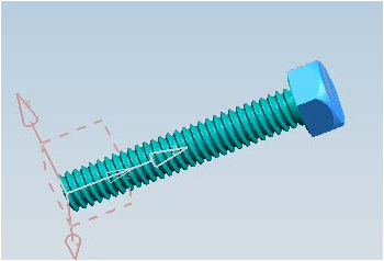
The hexagon bolt should now look like the following. Save the model.


Model a Hexagonal Screw


Create a new file and save it as Impeller_hexa-bolt

  • Choose INSERT → DESIGN FEATURE → CYLINDER
  • The cylinder should be pointing in the Z-direction with the center set at the origin and with the following dimensions:


Diameter = 0.25 inches
Height = 1.5 inches


Now create a small step cylinder on top of the existing cylinder.

  • The dimensions of this cylinder are,

Diameter = 0.387 inches
Height = 0.0156 inches 


  • On the Point Constructor window,click the Center icon at the top
  • Click on the top face of the existing

cylinder as shown in the following figure


Under the Boolean drop-down menu,
choose UNITE


The two cylinders should look like the figure shown below.


Save the model.
Next, we will create a hexagon for the head of the bolt.


  • Choose the icon from the Curves Toolbar as shown


  • On the Polygon window, type 6 for the number of sides


  • Click OK


There are three ways to draw the polygon.
• Inscribed Radius
• Side of Polygon
• Circumscribed Radius

  • Choose SIDE OF POLYGON


On the next window, enter the following dimensions.
Side = 0.246 inches
Orientation Angle = 0.00 degree

  • Click OK
  • On the Point Constructor window, again choose the Center icon
  • Click on the top face of the last cylinder drawn 

The polygon will be seen as shown below. 
If the model is not in wireframe, click on the Wireframe icon in the View Toolbar


Now we will extrude this polygon.

  • Choose INSERT → DESIGN FEATURE → EXTRUDE
  • Click on all six lines of the hexagon to choose the surface that is required to be extruded
  • Enter the End Distance as 0.1876 inches

The model looks like the following after extrusion


On top of the cylinder that has a diameter of 0.387 inches, insert another cylinder with the following dimensions.


Diameter = 0.387 inches
Height = 0.1875 inches


You will only be able to see this cylinder when the model is in wireframe since the cylinder is inside the hexagon head. The model will look like the following.


We will now use the feature operation Intersect.

  • Choose INSERT → DESIGN FEATURE → SPHERE
  • Choose DIAMETER, CENTER


  • Enter the value of the diameter as 0.55 inches and click OK
  • On the Point Constructor window, choose the Center icon
  • Select the bottom of the last cylinder drawn, which is inside the hexagon head and has a diameter of 0.387 inches and a height of 0.1875 inches as shown below

Click OK


This will give take you the next Dialog box which will ask you to choose the Boolean operation to be performed.


  • Choose INTERSECT


It will ask you to select the target solid


  • Choose the hexagonal head as shown 


  • Click CANCEL


This will give you the hexagonal bolt as shown below.


Check here how to add threading to the above bolt in the next post:


http://unigraphicsbasicsnmaterial.blogspot.com/2011/12/threading-of-hexagonal-bolt.html

Tuesday, 22 November 2011

HIDING & SHOWING ENTITIES


Whenever you create a sketch-based feature, the sketch used to create it is retained on the screen, even after the feature is created. NX allows you to hide the sketches or any other entity on the screen using the Hide tool. To invoke this tool, press the CTRL+B keys; the Class Selection dialog box will be displayed. Alternatively, you can invoke the Hide tool from the Utility toolbar. Select the sketch or any other entity from the screen using this dialog box and choose the OK button; the selected entities will be hidden


SHOWING HIDDEN ENTITIES

To restore the display of the hidden entities, press the SHIFT+CTRL+K keys; the Class Selection dialog box and the hidden entities will be displayed. Also, you will be prompted to select the objects to be displayed. Select the entities to be displayed and then choose the OK button.


HIDING ALL ENTITIES USING A SINGLE TOOL

NX allows you to hide all entities (all datum planes, coordinate systems, sketches,faceted bodies, solid bodies, and so on) from the drawing window, using a single tool.To do so, choose the Show and Hide button from the Utility toolbar; the Show and Hide dialog box will be displayed, as shown in Figure 


click on image to enlarge
All entities are divided into three categories, Bodies, Sketches, and Datums. Select the minus sign (-) from the respective rows; the corresponding entities will be hidden. For example, if you need to hide all the sketches in the drawing window, select the minus sign (-) from the Sketches row; all the sketches will be hidden. Similarly, to show hidden entities, select the plus sign (+) from the respective row; all entities under that category will be re-displayed in the drawing window.


Toolbar: Utility > Show
Toolbar: Utility > Show and Hide


TIP:The Show and Hide tool is very useful while working with complicated models and assemblies, where datums planes, coordinate systems, and sketches are in large numbers.You can also invoke this tool by pressing the CTRL+W keys.


Thursday, 10 November 2011

UG hot keys

Edit-Undo List-Invalid menu entry            
Ctrl+Z              
UG_EDIT_UNDO                            
Edit-Cut                                     
Ctrl+X              
UG_EDIT_CUT                             
Edit-Copy                                     
Ctrl+C              
UG_EDIT_COPY                            
Edit-Paste                                   
Ctrl+V              
UG_EDIT_PASTE                           
Edit-Delete...                               
Ctrl+D               
UG_EDIT_DELETE                          
Edit-Selection-Top Selection Priority - Feature F
UG_SEL_FEATURE_PRIORITY          
Edit-Selection-Top Selection Priority - Face  G
UG_SEL_FACE_PRIORITY                    
Edit-Selection-Top Selection Priority - Body  B
UG_SEL_BODY_PRIORITY                    
Edit-Selection-Top Selection Priority - Edge  E
UG_SEL_EDGE_PRIORITY                     
Edit-Selection-Top Selection Priority - Component C
UG_SEL_COMPONENT_PRIORITY
Edit-Selection-Select All                    
Ctrl+A              
UG_SEL_SELECT_ALL                       
Edit-Blank-Blank...                           
Ctrl+B              
UG_EDIT_BLANK_SELECTED                  
Edit-Blank-Reverse Blank All                 
Ctrl+Shift+B        
UG_EDIT_REVERSE_BLANK_ALL
Edit-Blank-Unblank Selected...               
Ctrl+Shift+K        
UG_EDIT_UNBLANK_SELECTED
Edit-Blank-Unblank All of Part               
Ctrl+Shift+U        
UG_EDIT_UNBLANK_ALL_OF_PART
Edit-Transform...                            
Ctrl+T              
UG_EDIT_TRANSFORM                        
Edit-Object Display...                       
Ctrl+J              
UG_EDIT_OBJECT_DISPLAY                  
View-Operation-Zoom...                       
Ctrl+Shift+Z        
UG_VIEW_ZOOM                            
View-Operation-Rotate...                     
Ctrl+R              
UG_VIEW_ROTATE                          
View-Operation-Section...                    
Ctrl+H              
UG_VIEW_SECTIONING                      
View-Layout-New...                            
Ctrl+Shift+N        
UG_LAYOUT_NEW                           
View-Layout-Open...                          
Ctrl+Shift+O        
UG_LAYOUT_OPEN                          
View-Layout-Fit All Views                    
Ctrl+Shift+F        
UG_LAYOUT_FIT_ALL_VIEWS                 
View-Visualization-High Quality Image
Ctrl+Shift+H        
UG_VIEW_HIGH_QUALITY_IMAGE
View-Information Window                                      
F4  
UG_VIEW_INFO_WINDOW
View-Current Dialog                         
F3                  
UG_VIEW_CURRENT_DIALOG
View-Reset Orientation                       
Ctrl+F8             
UG_VIEW_RESET_ORIENTATION
Format-Layer Settings...                      
Ctrl+L              
UG_LAYER_SETTINGS                       
Format-Visible in View...                    
Ctrl+Shift+V        
UG_LAYER_VIEW                           
Format-WCS-Display                                              
W 
UG_WCS_DISPLAY                          
File-New...                                  
Ctrl+N              
UG_FILE_NEW                             
File-Open...                                 
Ctrl+O              
UG_FILE_OPEN                             
File-Save                                    
Ctrl+S              
UG_FILE_SAVE_PART                       
File-Save As...                              
Ctrl+Shift+A        
UG_FILE_SAVE_AS                         
File-Plot...                                 
Ctrl+P              
UG_FILE_PLOT                            
File-Execute-Grip...                        
Ctrl+G              
UG_FILE_RUN_GRIP                        
File-Execute-Debug Grip...                    
Ctrl+Shift+G        
UG_FILE_RUN_GRIP_DEBUG                  
File-Execute-NX Open...                      
Ctrl+U              
UG_FILE_RUN_UFUN                        
Tools-Expression...                          
Ctrl+E              
UG_INSERT_DLEXPRESSION                  
Tools-Journal-Play...                        
Alt+F8              
UG_JOURNAL_PLAY                         
Tools-Journal-Edit                           
Alt+F11             
UG_JOURNAL_EDIT                          
Tools-Macro-Start Record...                  
Ctrl+Shift+R        
UG_MACRO_RECORD                         
Tools-Macro-Playback...                      
Ctrl+Shift+P        
UG_MACRO_PLAYBACK                       
Tools-Macro-Step...                           
Ctrl+Shift+S        
UG_MACRO_STEP                           
Preferences-Object...                        
Ctrl+Shift+J        
UG_PREFERENCES_OBJECT                   
Preferences-Selection...                     
Ctrl+Shift+T        
UG_PREFERENCES_SELECTION                
Information-Object...                        
Ctrl+I              
UG_INFO_OBJECT                          
Analysis-Curve-Refresh Curvature Graphs
Ctrl+Shift+C        
UG_INFO_MB_SHOW_GRAPHS                  
Application-Modeling...                      
Ctrl+M              
UG_APP_MODELING                         
Application-Shape Studio...                  
Ctrl+Alt+S          
UG_APP_STUDIO                           
Application-Drafting...                      
Ctrl+Shift+D        
UG_APP_DRAFTING                         
Application-Manufacturing...                  
Ctrl+Alt+M          
UG_APP_MANUFACTURING                    
Application-Sheet Metal-NX Sheet Metal
Ctrl+Alt+N          
UG_APP_SBSM                             
Application-Gateway...                       
Ctrl+W              
UG_APP_GATEWAY                          
Help-On Context...                          
F1                  
UG_HELP_ON_CONTEXT     
                 
Related Posts Plugin for WordPress, Blogger...