Showing posts with label SKETCHER. Show all posts

Tuesday, 22 November 2011

HIDING & SHOWING ENTITIES


Whenever you create a sketch-based feature, the sketch used to create it is retained on the screen, even after the feature is created. NX allows you to hide the sketches or any other entity on the screen using the Hide tool. To invoke this tool, press the CTRL+B keys; the Class Selection dialog box will be displayed. Alternatively, you can invoke the Hide tool from the Utility toolbar. Select the sketch or any other entity from the screen using this dialog box and choose the OK button; the selected entities will be hidden


SHOWING HIDDEN ENTITIES

To restore the display of the hidden entities, press the SHIFT+CTRL+K keys; the Class Selection dialog box and the hidden entities will be displayed. Also, you will be prompted to select the objects to be displayed. Select the entities to be displayed and then choose the OK button.


HIDING ALL ENTITIES USING A SINGLE TOOL

NX allows you to hide all entities (all datum planes, coordinate systems, sketches,faceted bodies, solid bodies, and so on) from the drawing window, using a single tool.To do so, choose the Show and Hide button from the Utility toolbar; the Show and Hide dialog box will be displayed, as shown in Figure 


click on image to enlarge
All entities are divided into three categories, Bodies, Sketches, and Datums. Select the minus sign (-) from the respective rows; the corresponding entities will be hidden. For example, if you need to hide all the sketches in the drawing window, select the minus sign (-) from the Sketches row; all the sketches will be hidden. Similarly, to show hidden entities, select the plus sign (+) from the respective row; all entities under that category will be re-displayed in the drawing window.


Toolbar: Utility > Show
Toolbar: Utility > Show and Hide


TIP:The Show and Hide tool is very useful while working with complicated models and assemblies, where datums planes, coordinate systems, and sketches are in large numbers.You can also invoke this tool by pressing the CTRL+W keys.


Tuesday, 15 November 2011

Lesson: Sketcher-Introduction


when a feature is created from a sketch, the feature is "associated" with the sketch, and is parametrically controlled by the sketch. Therefore, if you edit a sketch, any associated features are updated.
So mainly the purpose of the sketch is to make design fully parametric.

Instructions  for creating a Sketch:

•Establish the design intent for the feature or part that you want to model.
•Follow standards(generally depends on requirement) to set up the layers and/or categories for the sketches that you plan to create. 
(It is usually a good idea to place each sketch on its own layer.)
•Check and set the sketch preferences.
•Create the sketch and the sketch geometry.
•Constrain the sketch according to your design intent.
•Use the sketch to develop a feature on your model.

Constraints:

    Geometrical Constraints:

•Horizontal
•Vertical
•Concentric
•Same radius
•Collinear

    Dimensional Constraints:

•Horizontal distance
•Vertical distance
•Radial dimension
•Center to Center dist

Toolbar for Sketch:

Basic features in Sketch Tool Bar


DOF:

Over Constraint:
It will be shown in Yellow color

Try Your Self:
(Tools will be Explained later)

Basic Fig for your Practice

Thursday, 10 November 2011

Exercise: how to use the constraints tool

Draw the sketch shown below:
Sketch you need to draw

Once the sketch is complete, we will constrain the sketch. It is better to apply the geometric constraints before giving the dimensional constraints.
>>> Choose INSERT → CONSTRAINTS or click on the Constraints icon in the side toolbar
You will be able to see all the degrees of freedom on the screen represented by orange arrows.
orange color arrows are the no of DOF to be 
constrained
We will start by constraining between an entity in the sketch and the datum or fixed reference.
As an example, we will place the center of the arc at the origin. We can use the two default X and Y axes as a datum reference.
> Select the Y-axis and then the center of the arc, which is marked by the intersection of the yellow arrows. The center of the arc will be marked by a red asterisk once it has been selected
> Click the Point on Curve icon


>Repeat the same procedure to place the center of the arc on the X-axis
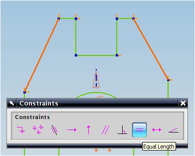
> Select the two slanted lines and make them equal in length


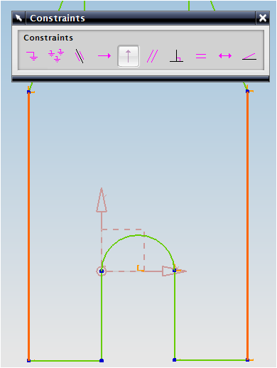
> Similarly select the two long vertical lines and make them equal in length


Select the bottom two horizontal lines and make them collinear and then click on the same lines and make them equal in length


If you DO NOT find the two Blue circles (Tangent Constraints) near the semicircle as shown in the figure, follow the below steps. Otherwise, you can ignore this and skip down to the dimensional constraints.


>Select the circular arc and one of the two vertical lines connected to its endpoints
> Select the Tangent icon


If the arc and line is already tangent to each other, the icon will be grayed out. If that is the case click on EDIT → SELECTION →, DESELECT ALL. Repeat the same procedure for the arc and the other vertical line.


>Select the two vertical lines and make them equal


> Similarly select the two small horizontal lines and make them collinear and equal


>Similarly select the two vertical lines and make them equal


So far, we have created all the geometric constraints. Now we have to create the dimensional constraints. You will find that as we add on dimensions, the degrees of freedom represented by the yellow arrows will disappear.


It is always better to apply the geometry constraints first. If there is any conflict between the dimensional and geometric constraints, those
entities will be highlighted in yellow.
> Choose the Inferred Dimensions icon in the Constraints toolbar
> Add on all the dimensions as shown in the following figure


For example, to create a dimension for the top two corners, you may have to click on the arrow next to the Inferred Dimensions icon and click on the Horizontal icon. Then click somewhere near the top of the two diagonal lines to select them. While dimensioning, if you find the dimensions illegible, but do not worry about editing the dimensions now. Make sure the small arrows are disappearing as constraints are placed.


All dimensions are given after Geometrical Constraints
Now we will edit all the dimension values one by one. It is highly recommended to start editing from the biggest dimension first and move to the smaller dimensions. 
> Edit the values as shown in the figure below. Double click on each dimension to change the values to the values as shown in figure below:
Fully Constrained Sketch


> Click on the Finish flag on the top left corner of the screen when you are finished


Wednesday, 9 November 2011

Lesson:Sketcher Toolbar

Orient View to Sketch:

If the model file is rotated during the process of sketching, click on this icon to view the sketch on a plane parallel to the screen.

Reattach Sketch:

This function allows you to reattach the sketch to the desired plane without recreating all the curves, dimensions, and constraints.

Update Model:

When you make changes in a sketch, click on this icon to see the effects of those changes without exiting the Sketch mode


Lesson:Constraints Toolbar

  All the curves are created by picking points. For example, a straight line is created with two points. 
  In a 2-D environment, any point will have two degrees of freedom, one along X and another along Y. The number of points depends on the type of curve being created. 
  Therefore, a curve entity will have twice the number of degrees of freedom than the number of points it comprises. These degrees of freedom can be removed by creating a constraint with a fixed entity.
  In fact, it is recommended that you remove all these degrees of freedom by relating the entities directly or indirectly to the fixed entities. It can be done by giving dimensional or geometric properties like Parallelity, Perpendicularity, etc.
(Note: These degrees of freedom will be displayed in orange arrows . All these arrows should be removed by applying the constraints to follow a disciplined modeling.)


Dimensional Constraints:


  The degrees of freedom can be eliminated by giving dimensions with fixed entities like axes,planes, the coordinate system or any existing solid geometries created in the model.
  These dimensions can be linear, radial, angular etc. You can edit the dimensional values at anytime during sketching by double-clicking on the dimension.


Geometric Constraints:


  Besides the dimensional constraints, some geometric constraints can be given to eliminate the degrees of freedom. They include parallel, perpendicular, collinear, concentric, horizontal,vertical, equal length, etc.
  The software has the capability to find the set of possible constraints for the selected entities.


Show all Constraints:


  Clicking this icon will show all the options pertaining to the entities in that particular sketch in white.


Show/Remove Constraints:


  This window lists all the constraints and types of constraints pertaining to any entity selected.
  You can delete any of the listed constraints or change the sequence of the constraints


Lesson:Sketch Curve Toolbar


NX sketch is a named set of curves joined in a string that when swept, form a solid. The sketch represents the outer boundary of that part. The curves are created on a plane in the sketcher. In the beginning, these curves are drawn without any exact dimensions. The solids created can be united into single parts using constraints. There are two kinds of constraints: 
1) Geometric constraints
2) Dimensional constraints

These are the different ways that you can use sketches:
• A sketch can be revolved


• A sketch can be extruded


• A sketch can be swept along a guide (line)

The advantages of sketching over using primitives are,
a) The curves used to create the profile outline are very flexible and can be used to model unusual shapes.
b) The curves are parametric, hence associative and they can easily be changed or removed.
c) If the plane in which the sketch is drawn is changed, the sketch will be changed accordingly.
d) Sketches are useful when you want to control an outline of a feature, especially if it may need to be changed in the future. Sketches can be edited very quickly and easily


Sketch Curve Toolbar:

This toolbar contains icons for creating basic curves and spline curves, editing, extending,trimming, filleting etc. Each type of curve will have different methods of selection. Let us discuss the most frequently used options.
Profile:
This option creates both straight lines as well as arcs depending on the icon you select in the popup toolbar. You can pick the points by using the coordinate system or by entering the length and angle of the line as shown in the following figures.


Line:

This option will selectively create only straight lines.


Arc:
This option creates arcs by either of two methods. The first option creates arc with three sequential points as shown below.


The second option creates the arc with a center point, radius and sweep angle or by center point with a start point and end point. The illustration is shown below:


Circle:
Creating a circle is similar to creating an arc, except that the circle is closed unlike an arc.


Quick Trim:
This trims the extending curves from the points of intersection of the curves. This option reads every entity by splitting them if they are intersected by another entity and erases the portion selected.


Studio Spline:
You can create basic spline curves (B-spline and Bezier) with poles or through points with the desired degree of the curve. The spline will be discussed in detail in the next chapter (Freeform Features).


Related Posts Plugin for WordPress, Blogger...