Draw the sketch shown below:
Once the sketch is complete, we will constrain the sketch. It is better to apply the geometric constraints before giving the dimensional constraints.
>>> Choose INSERT → CONSTRAINTS or click on the Constraints icon in the side toolbar
You will be able to see all the degrees of freedom on the screen represented by orange arrows.
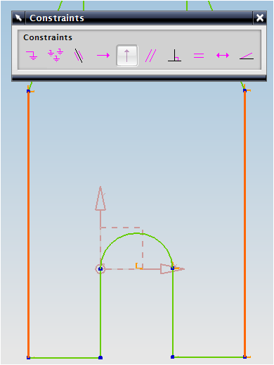
As an example, we will place the center of the arc at the origin. We can use the two default X and Y axes as a datum reference.
> Select the Y-axis and then the center of the arc, which is marked by the intersection of the yellow arrows. The center of the arc will be marked by a red asterisk once it has been selected
> Click the Point on Curve icon

>Repeat the same procedure to place the center of the arc on the X-axis
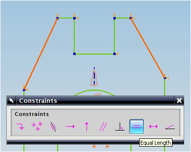
> Select the two slanted lines and make them equal in length

> Similarly select the two long vertical lines and make them equal in length

Select the bottom two horizontal lines and make them collinear and then click on the same lines and make them equal in length

If you DO NOT find the two Blue circles (Tangent Constraints) near the semicircle as shown in the figure, follow the below steps. Otherwise, you can ignore this and skip down to the dimensional constraints.
>Select the circular arc and one of the two vertical lines connected to its endpoints
 > Select the Tangent icon
If the arc and line is already tangent to each other, the icon will be grayed out. If that is the case click on EDIT → SELECTION →, DESELECT ALL. Repeat the same procedure for the arc and the other vertical line.

>Select the two vertical lines and make them equal

> Similarly select the two small horizontal lines and make them collinear and equal

>Similarly select the two vertical lines and make them equal

So far, we have created all the geometric constraints. Now we have to create the dimensional constraints. You will find that as we add on dimensions, the degrees of freedom represented by the yellow arrows will disappear.
It is always better to apply the geometry constraints first. If there is any conflict between the dimensional and geometric constraints, those
entities will be highlighted in yellow.
> Choose the Inferred Dimensions icon in the Constraints toolbar
> Add on all the dimensions as shown in the following figure
For example, to create a dimension for the top two corners, you may have to click on the arrow next to the Inferred Dimensions icon and click on the Horizontal icon. Then click somewhere near the top of the two diagonal lines to select them. While dimensioning, if you find the dimensions illegible, but do not worry about editing the dimensions now. Make sure the small arrows are disappearing as constraints are placed.
Now we will edit all the dimension values one by one. It is highly recommended to start editing from the biggest dimension first and move to the smaller dimensions.
> Edit the values as shown in the figure below. Double click on each dimension to change the values to the values as shown in figure below:
> Click on the Finish flag on the top left corner of the screen when you are finished
 |
| Sketch you need to draw |
Once the sketch is complete, we will constrain the sketch. It is better to apply the geometric constraints before giving the dimensional constraints.
>>> Choose INSERT → CONSTRAINTS or click on the Constraints icon in the side toolbar
You will be able to see all the degrees of freedom on the screen represented by orange arrows.
 |
| orange color arrows are the no of DOF to be |
constrained
We will start by constraining between an entity in the sketch and the datum or fixed reference.As an example, we will place the center of the arc at the origin. We can use the two default X and Y axes as a datum reference.
> Select the Y-axis and then the center of the arc, which is marked by the intersection of the yellow arrows. The center of the arc will be marked by a red asterisk once it has been selected
> Click the Point on Curve icon

>Repeat the same procedure to place the center of the arc on the X-axis
> Select the two slanted lines and make them equal in length
> Similarly select the two long vertical lines and make them equal in length
Select the bottom two horizontal lines and make them collinear and then click on the same lines and make them equal in length

If you DO NOT find the two Blue circles (Tangent Constraints) near the semicircle as shown in the figure, follow the below steps. Otherwise, you can ignore this and skip down to the dimensional constraints.
>Select the circular arc and one of the two vertical lines connected to its endpoints
If the arc and line is already tangent to each other, the icon will be grayed out. If that is the case click on EDIT → SELECTION →, DESELECT ALL. Repeat the same procedure for the arc and the other vertical line.
>Select the two vertical lines and make them equal

> Similarly select the two small horizontal lines and make them collinear and equal

>Similarly select the two vertical lines and make them equal

So far, we have created all the geometric constraints. Now we have to create the dimensional constraints. You will find that as we add on dimensions, the degrees of freedom represented by the yellow arrows will disappear.
It is always better to apply the geometry constraints first. If there is any conflict between the dimensional and geometric constraints, those
entities will be highlighted in yellow.
> Choose the Inferred Dimensions icon in the Constraints toolbar
> Add on all the dimensions as shown in the following figure
For example, to create a dimension for the top two corners, you may have to click on the arrow next to the Inferred Dimensions icon and click on the Horizontal icon. Then click somewhere near the top of the two diagonal lines to select them. While dimensioning, if you find the dimensions illegible, but do not worry about editing the dimensions now. Make sure the small arrows are disappearing as constraints are placed.
 |
| All dimensions are given after Geometrical Constraints |
> Edit the values as shown in the figure below. Double click on each dimension to change the values to the values as shown in figure below:
 |
| Fully Constrained Sketch |
> Click on the Finish flag on the top left corner of the screen when you are finished
No comments:
Post a Comment