Modeling Environment Toolbars
You can invoke the Modeling environment, if it is not already invoked, by choosing the Modeling button from the Application toolbar. Alternatively, you can choose Start > Modeling from the Standard toolbar.
The toolbars in the Modeling environment are discussed next.
View Toolbar
The tools in the View toolbar, as shown in Figure,are used for manipulating the views of the model. The View toolbar is available in all the environments. Some of the buttons in the View toolbar are not available in the Drafting environment.

Feature Toolbar
The tools in this toolbar, as shown in Figure, are used to convert a sketch drawn in the Sketcher environment into a feature. This toolbar contains sketch-based feature tools and placed feature tools. You can create the datum plane, axis, and points using the tools in this toolbar

Sketcher Environment Toolbar
The Sketch button in the Feature toolbar is used to invoke the Sketcher environment, where you can create the sketch. After choosing the Sketch button, select a plane, or a planar face to invoke the Sketcher environment. The toolbars in the Sketcher environment are discussed next.
Sketcher Toolbar
The Finish Sketch button in the Sketcher toolbar is used to switch back to the
Modeling environment, where you can convert the sketch into a feature. Figure shows the buttons that are available in the Sketcher toolbar.

Sketch Tools Toolbar
It is one of the most important toolbars in the Sketcher environment. The tools in the Sketch Tools toolbar are used to draw the sketches as well as edit the drawn sketches. Additionally,you can apply constrains to the geometric entities and assign dimension to a sketch using the tools in this toolbar. You can make a sketch fully defined using these tools. Figure shows the buttons that are available in the Sketch Tools toolbar.

Once the basic sketch is complete, you need to convert it into a feature. Choose the Finish Sketch button from the Sketcher toolbar and switch back to the Modeling environment.
The remaining toolbars in the Modeling environment are discussed next.
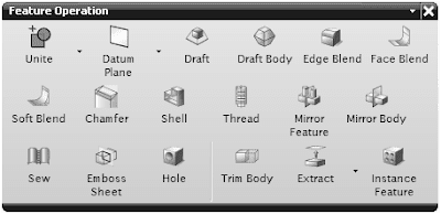
Feature Operation Toolbar
The tools in the Feature Operation toolbar are used to apply the placed features such as taper, fillet, hole, shell, and so on. Figure shows the buttons in the Feature Operation toolbar
Surface Design Toolbars
You can create the surface design in the same Modeling environment. A separate environment is not required to create the surface design. The tools used to create the solid bodies are also used to create the surface bodies. Some of the toolbars used to create the surface design are discussed next.
Surface Toolbar
The tools in the Surface toolbar are used to create complicated surfaces. Figure shows

Freeform Shape Toolbar
The tools in the Freeform Shape toolbar are used to create advanced surfaces.
Figure shows the Freeform Shape toolbar.

Assemblies Environment Toolbars
You can create the assembly in the same Modeling environment. The toolbars that are used for the assembly can be invoked by choosing Start > Assemblies from the Standard toolbar.
Alternatively, choose the Assemblies button from the Application toolbar. The toolbars used in the assembly design are discussed next.
Assemblies Toolbar
The tools in the Assemblies toolbar are used to insert an existing part or assembly in the current assembly file. You can also create a new component in the assembly file using the tools in this toolbar. Figure shows the buttons in the Assemblies toolbar.

Drafting Environment Toolbars
To invoke the Drafting environment, choose the Drafting button from the Application toolbar.Alternatively, this environment can be invoked by choosing Start > Drafting from the Standard toolbar. The toolbars in the Drafting environment are discussed next.
Drawing Toolbar
The tools in the Drawing toolbar are used to insert a new sheet, create a new view, generate an orthographic view, section view, and detail views for a solid part or an assembly. Figure shows the Drawing Layout toolbar.

Dimension Toolbar
The tools in the Dimension toolbar are used to generate various dimensions in the drawing views. Figure shows the Dimension toolbar.

Drafting Annotation Toolbar
The tools in the Drafting Annotation toolbar are used to generate the GDT parameters,annotations, symbols, and so on. Figure shows the Drafting Annotation toolbar.

Synchronous Modeling Toolbar
The Synchronous Modeling Technology is one of the latest enhancements in
NX. A separate toolbar named as Synchronous Modeling toolbar consisting of
26 tools is introduced in NX 6. The tools available in this toolbar are used to
modify and improve an existing design in the shortest period of time. Figure shows the Synchronous Modeling toolbar

You can invoke the Modeling environment, if it is not already invoked, by choosing the Modeling button from the Application toolbar. Alternatively, you can choose Start > Modeling from the Standard toolbar.
The toolbars in the Modeling environment are discussed next.
View Toolbar
The tools in the View toolbar, as shown in Figure,are used for manipulating the views of the model. The View toolbar is available in all the environments. Some of the buttons in the View toolbar are not available in the Drafting environment.

Feature Toolbar
The tools in this toolbar, as shown in Figure, are used to convert a sketch drawn in the Sketcher environment into a feature. This toolbar contains sketch-based feature tools and placed feature tools. You can create the datum plane, axis, and points using the tools in this toolbar

Sketcher Environment Toolbar
The Sketch button in the Feature toolbar is used to invoke the Sketcher environment, where you can create the sketch. After choosing the Sketch button, select a plane, or a planar face to invoke the Sketcher environment. The toolbars in the Sketcher environment are discussed next.
Sketcher Toolbar
The Finish Sketch button in the Sketcher toolbar is used to switch back to the
Modeling environment, where you can convert the sketch into a feature. Figure shows the buttons that are available in the Sketcher toolbar.

Sketch Tools Toolbar
It is one of the most important toolbars in the Sketcher environment. The tools in the Sketch Tools toolbar are used to draw the sketches as well as edit the drawn sketches. Additionally,you can apply constrains to the geometric entities and assign dimension to a sketch using the tools in this toolbar. You can make a sketch fully defined using these tools. Figure shows the buttons that are available in the Sketch Tools toolbar.

Once the basic sketch is complete, you need to convert it into a feature. Choose the Finish Sketch button from the Sketcher toolbar and switch back to the Modeling environment.
The remaining toolbars in the Modeling environment are discussed next.
Feature Operation Toolbar
The tools in the Feature Operation toolbar are used to apply the placed features such as taper, fillet, hole, shell, and so on. Figure shows the buttons in the Feature Operation toolbar

Surface Design Toolbars
You can create the surface design in the same Modeling environment. A separate environment is not required to create the surface design. The tools used to create the solid bodies are also used to create the surface bodies. Some of the toolbars used to create the surface design are discussed next.
Surface Toolbar
The tools in the Surface toolbar are used to create complicated surfaces. Figure shows

Freeform Shape Toolbar
The tools in the Freeform Shape toolbar are used to create advanced surfaces.
Figure shows the Freeform Shape toolbar.

Assemblies Environment Toolbars
You can create the assembly in the same Modeling environment. The toolbars that are used for the assembly can be invoked by choosing Start > Assemblies from the Standard toolbar.
Alternatively, choose the Assemblies button from the Application toolbar. The toolbars used in the assembly design are discussed next.
Assemblies Toolbar
The tools in the Assemblies toolbar are used to insert an existing part or assembly in the current assembly file. You can also create a new component in the assembly file using the tools in this toolbar. Figure shows the buttons in the Assemblies toolbar.

Drafting Environment Toolbars
To invoke the Drafting environment, choose the Drafting button from the Application toolbar.Alternatively, this environment can be invoked by choosing Start > Drafting from the Standard toolbar. The toolbars in the Drafting environment are discussed next.
Drawing Toolbar
The tools in the Drawing toolbar are used to insert a new sheet, create a new view, generate an orthographic view, section view, and detail views for a solid part or an assembly. Figure shows the Drawing Layout toolbar.

Dimension Toolbar
The tools in the Dimension toolbar are used to generate various dimensions in the drawing views. Figure shows the Dimension toolbar.

Drafting Annotation Toolbar
The tools in the Drafting Annotation toolbar are used to generate the GDT parameters,annotations, symbols, and so on. Figure shows the Drafting Annotation toolbar.

Synchronous Modeling Toolbar
The Synchronous Modeling Technology is one of the latest enhancements in
NX. A separate toolbar named as Synchronous Modeling toolbar consisting of
26 tools is introduced in NX 6. The tools available in this toolbar are used to
modify and improve an existing design in the shortest period of time. Figure shows the Synchronous Modeling toolbar

Nx Unigraphics Tutorial: Lesson: Toolbars In All Modules >>>>> Download Now
ReplyDelete>>>>> Download Full
Nx Unigraphics Tutorial: Lesson: Toolbars In All Modules >>>>> Download LINK
>>>>> Download Now
Nx Unigraphics Tutorial: Lesson: Toolbars In All Modules >>>>> Download Full
>>>>> Download LINK 98