Showing posts with label INTRODUCTION TO UG. Show all posts

Tuesday, 15 May 2012

Geometry selection for designing in an assembly context


You can now easily select geometry outside the work part for many NX
Modeling commands. You can automatically copy geometry you select outside
the work part into the work part as either WAVE geometry (which updates
when the source geometry changes) or non-associative geometry (which does
not update).


This functionality uses two new options on the Selection bar: (1) Select
Scope and (2) Create Interpart Link.
You can control interpart selection with the Select Scope option to select
geometry from assembly components other than the work part.
Select Scope options are:
• Entire Assembly
Use this option to select geometry from any component in the assembly.
• Within Work Part and Components
Use this option to limit the selection of geometry to the current work part
and its components, if it is a subassembly.
• Within Work Part Only
Use this option to limit the selection of geometry to the current work part.
If the Select Scope option is not available for a command, this indicates that
the command does not support this design in context functionality. In this
case, you can still use one of the other traditional methods to create interpart
links, such as Wave Geometry Linker.
When selecting geometry from a component other than the work part, you
may choose to create an interpart link or to use the geometry unassociatively.
To create an interpart link, turn on the Create Interpart Link option before
making a selection. For commands where you make multiple selections, you
can turn this option on or off independently for each selection.

Wednesday, 18 April 2012

Assembly Load Option


To define how and where NX load part file, we need to configure some basic function like, save, open and assembly.
Dialog box will appear, like the below picture, from the dialog box here we can set up load the file first time as may be required, it is easier for us in working with Unigraphic later.


 1. Part version
You can set whether each time to load a new file or open a file starting from the folder, or history. UGS default is the folder.
2. scope
You can choose all the components directly on the load time, or just based on the stored data, or other options, are generally used are all components (including part assembly).
3.Reference Sets
You can call the components as per the reference set created while modeling.


4. Save Load option
Save to file, serve to redirect the folder to load the first time, after the set, every time you open a new file, the folder will be automatically redirected to it.
So is the open from the file, after we set the folder, each time it opens the file it will automatically be redirected to a folder that was set.

Saturday, 25 February 2012

Difference between Chamfer and Blend


1.Blend:
Blend operations add or subtract material to round (fillet) edges.
• Uni graphics provides 3 kinds of blends:
Edge Blend
• Is the only type of blend you need to know how to perform for this class.
• Can be constant or variable radius.
• Good practice rule:
Face Blends
• In face blends you choose two faces instead of an edge.
• Face Blends will trim faces if required.
Soft Blends
• Soft blends are used for styled “Class A” surfaces.
• The curvature varies smoothly


2.Chamfers
• Chamfer add or remove material to create beveled edges.
• The same rules apply to creating chamfers as to creating edge blends.
• Options include:
– Single offset
– Double offset
– Offset and Angle

Wednesday, 11 January 2012

FORM FEATURES -2


Reference Features
These let you create reference planes or reference axes. These references can assist you in creating features on cylinders, cones, spheres and revolved solid bodies.
􀂾 Click on INSERT → DATUM/POINT to view the different Reference Feature options:
Datum Plane, Datum Axis, Datum CSYS, and Point 


Swept Features
These let you create bodies by extruding or revolving sketch geometry. Swept Features include:
• Extruded Body
• Revolved Body
• Sweep along Guide
• Tube
• Styled Sweep


To select a swept feature you can do the following:
􀂾 Click on INSERT → DESIGN FEATURE for Extrude and Revolve
or
􀂾 Click on INSERT → SWEEP for the rest of the options


Remove Features
Remove Features let you create bodies by removing solid part from other parts.
􀂾 Click on INSERT → DESIGN FEATURE
Remove Features include,
• Hole
• Boss
• Pocket
• Pad
• Slot
• Groove


You can also select the features by clicking on the icons


User-Defined features
These allow you to create your own form features to automate commonly used design elements.
You can use user-defined features to extend the range and power of the built-in form features.
􀂾 Click on INSERT → DESIGN FEATURE → USER DEFINED


Extract Features
These features let you create bodies by extracting curves, faces and regions. These features are widely spaced under Associative Copy and Offset/Scale menus. 


Extract Features include:
• Extract
• Sheet from curves
• Bounded plane
• Thicken Sheet
• Sheet to Solid Assistant
 Click on INSERT → ASSOCIATIVE
COPY → EXTRACT for Extract options
􀂾 Click on INSERT → OFFSET/SCALE for
Thicken Sheet and Sheets to Solid Assistant
􀂾 Click on INSERT → SURFACE for
Bounded Plane and Sheet from curves

Tuesday, 10 January 2012

FORM FEATURES


Features are objects that are associatively defined by one or more parents and that retain within the model the order of its creation and modification, thus capturing its history. Parents can be geometrical objects or numerical variables. Features include primitive, surface and solid objects,and certain wire frame objects (such as curves and associative trim and bridge curves). For example, some common features include blocks, cylinders, cones, spheres, extruded bodies, and revolved bodies.


TYPES OF FEATURES

There are six types of Form features: Reference features, Swept features, Remove features, User defined features, Extract features and Primitives.


Click INSERT on the Menu bar As you can see, the marked menus in the figure on the right side contain the commands of Form Features.


The Form Feature icons are grouped in the Form Features Toolbar as shown below. You can choose the icons that you use frequently.


􀂾 Click on the drop down arrow in Form Feature Toolbar
􀂾 Choose ADD OR REMOVE BUTTONS
􀂾 Choose FORM FEATURE


Saturday, 24 December 2011

Tool bars


Toolbars contain icons, which serve as shortcuts for many NX functions. The following figure shows the main Toolbar items normally displayed. However, you can find many more icons for different feature commands, based on the module selected and how the module is customized.


􀂾 Right-Click anywhere on the existing toolbars gives a list of
other Toolbars. You can add any of the toolbars by checking
them. 
The list of toolbars you can see in the default option is Standard, View, Visualization, Selection, Object Display, etc. Normally, the default setting should be sufficient for most operations but during certain operations, you might need additional toolbars. If you want to add buttons pertaining to the commands and toolbars, 


􀂾 Click on the pull-down arrow on any of the Toolbars and choose
ADD OR REMOVE BUTTONS.
􀂾 Choose CUSTOMIZE


This will pop up a Customize dialog window with all the Toolbars under ‘Toolbar’ Tab and commands pertaining to each Toolbar under ‘Commands’ tab. You can check all the toolbars that you wish to be displayed.


You can customize the settings of your NX interface by clicking on the Roles tab on the Resource Bar


The Roles tab has different settings of the toolbar menus that are displayed on the NX interface.


• It allows you to customize the toolbars you desire to be displayed in the Interface.
• Selecting Advanced shows all the Application Toolbars necessary for drafting and modeling.
• You can also select the Application Toolbars to be displayed in the Interface by clicking on the Industry Specific settings. This provides a list of industry
specific toolbar applications as shown below.


Wednesday, 23 November 2011

ROTATING THE VIEW OF A MODEL IN 3D SPACE


NX provides you with an option of rotating the view of a solid model freely in
3-dimensional (3D) space. This enables you to visually maneuver around the solid model and view it from any direction. To do so, choose the Rotate button from the View toolbar; the cursor changes to the rotate view cursor and you will be prompted to drag the cursor to rotate the model. Next, press and hold the left mouse button and drag the cursor; the view of the model will be rotated and you can visually maneuver around it.


You can also rotate the view around the X, Y, or Z-axis of the current view. To rotate the view around the X-axis of the current view, invoke the Rotate tool and move the cursor close to the left or right edge of the drawing window; the cursor changes to the X-rotate cursor. Press and hold the left mouse button and drag the cursor; the view will be rotated around the X-axis of the current view. Move the cursor close to the bottom edge of the drawing window and drag the cursor to rotate the view around the Y-axis of the current view. Similarly, move the cursor close to the top edge of the drawing window and drag the cursor to rotate the view around the Z-axis of the current view. Figure below shows the X, Y, and Z rotate cursors. 


Tuesday, 22 November 2011

SETTING DISPLAY MODES


You can set the display modes for the solid models using the buttons in the View toolbar. Figure shows the partial display of the View toolbar with various buttons and flyout options that you can use to set the display modes of the model


Monday, 21 November 2011

COLOR SCHEME


NX allows you to use various color schemes as the background screen color and also for displaying the solid bodies on the screen. To change the background color scheme, choose Preferences > Background from the menu bar; the Edit Background dialog box will be displayed.
Select the Plane radio button from the Shaded Views and Wireframe Views areas. Next,choose the color swatch available on the right side of the Plain Color option; the Color dialog box will be displayed. Select the White color swatch from the Colors dialog box and choose the OK button twice to apply the new color scheme to the NX environment. 
Note that all the files that you open henceforth will not use this color scheme.

Sunday, 20 November 2011

Bidirectional Associativity


NX has different environments such as the Modeling environment,
Assemblies environment and the Drafting environment. The bidirectional associativity that exists between all these environments ensures that any modification made in the model in any of the environments of NX, is automatically reflected in the other environments immediately. For example, if you modify the dimension of a part in the Modeling environment, the change will be reflected in the Assemblies and the Drawing environments.
Similarly, if you modify the dimensions of a part in the drawing views generated in the Drafting environment, the changes will be reflected in the Modeling and Assemblies environments. Consider the drawing views of the pipe housing shown in Figure
The drawing views of the body part before making the modifications


 When you modify the model in the Modeling environment, the changes will be reflected in the Drafting environment automatically. 
The drawing views after making the modifications
Figure shows the drawing views of the pipe housing after increasing the diameter and the number of holes.

Resource Bar,Roles,Part Navigator


Resource Bar
The Resource Bar combines all navigator windows, a history palette, an integrated web browser, and a parts template in one common place for a better user interface. By default, the Resource Bar is located on the left side of the NX window.


Roles
Roles are a set of system customized tools and toolbars used for different applications. In NX, you have different roles for different industrial applications. The Roles tab in the Resource Bar is used to activate the required role. In this book, the Essentials with fullmenus role has been used, as it contains all the required tools. To activate this role, choose the Roles tab from the Resource Bar and click on the System Defaults option, if it is not
expanded already; a flyout will be displayed. Click on the Essentials with full menus icon to activate that role. Figure shows the Roles navigator that appears when you choose the Roles tab in the Resource Bar.


Part Navigator
The Part Navigator keeps a track of all the operations that are carried out on the part.Figure shows the part navigator that appears when you choose the Part Navigator tab in the Resource Bar


File extension


*.prt
*.prt is a file extension associated with all the files that are created in the Sketcher, Modeling, Shape Studio, Assemblies, and Drafting environments of NX.

Parametric Modeling


The parametric nature of a software package is defined as its ability to use the standard properties or parameters in defining the shape and size of a geometry. The main function of this property is to derive the selected geometry to a new size or shape without considering its original dimensions. You can change or modify the shape and size of any feature at any stage
of the designing process. This property makes the designing process an easy task. For example, consider the design of the body of a pipe housing, as shown in Figure


To change the design by modifying the diameter of the holes and their number on the front, top, and the bottom face, you need to select the feature and change the diameter and the number of instances in the pattern. The modified design is shown in Figure


Friday, 18 November 2011

lesson:DIALOG BOXES IN NX

DIALOG BOXES IN NX:

To create any feature, you need to follow certain steps in a particular order. These steps are placed in a top-down order in the corresponding dialog boxes. This layout of dialog boxes will help you throughout the feature creation operation


The current selection step will be highlighted in orange. The required steps are marked with red asterisks, and the completed steps are marked with green check marks. 
The advanced options are collapsed and hidden in the rollouts. The button highlighted in green indicates the next default action.


The Reset button is used to reset the dialog box to its initial settings. The Hide Collapsed Groups button is used to hide all collapsed rollouts to simplify the dialog box..


 To view all the collapsed rollouts, choose the Show Collapsed Groups button, which will be available only after choosing the Hide Collapsed Groups button. The Close button is used to exit the dialog box.

Tuesday, 15 November 2011

Lesson: Coordinate system


COORDINATE SYSTEMS
Absolute Coordinate System:
The Absolute Coordinate System is the coordinate system from which all objects are referenced.


This is a fixed coordinate system and hence the locations and orientations of every object in NX modeling space are related back to its origin. The Absolute Coordinate System (or “Absolute CSYS”) also provides a common frame of reference between part files. An absolute position at X=1, Y=1, and Z=1 in one part file is the same location in any other part file as well.


Work Coordinate System:
The Work Coordinate System (WCS) is what you will use for construction
when you want to determine orientations and angles of features. The axes of the WCS are denoted XC, YC, and ZC. (The “C” stands for “current”.)
It is possible to have multiple coordinate systems in a part file, but only one of them can be the work coordinate system.


Existing Coordinate Systems:
You can create an “existing coordinate system” (CSYS) whenever you need to
return to a specific location and orientation in modeling space.


Move the WCS:
Here, you will learn how to translate and rotate the WCS.


Translate the WCS:
This procedure will move the WCS origin to any point
you specify, but the orientation (direction of the axes)
of the WCS will remain the same.


 Choose FORMAT →WCS → ORIGIN


The Point Constructor dialog is displayed in the figure.


You either can specify a point from the drop down menu at the top of the dialog box or by entering the XY- Z coordinates in the XC, YC, and ZC fields.


NX for Engineering Design 3 0 Missouri University of Science and Technology


A majority of the work will be in relation to the working coordinate system rather than the absolute coordinate system. The default is the WCS.
The default action button is Inferred Point. The button is highlighted as shown in the figure. The name of the active icon appears above the top row of action buttons.


This is the point on the object, which is closest to the cursor. It can be the center of circle or end-point of a line and so on.


 Click CANCEL


Rotate the WCS:
You can also rotate the WCS around one of its axes.
 Choose FORMAT →WCS → ROTATE
The Rotate WCS dialog is shown on the right side.
The dialog shows six different ways to rotate the WCS around an axis. These rotation procedures follow the right-hand rule of rotation. You can also specify the angle to which the WCS be rotated.


 Click CANCEL


Save the Current Location and Orientation of the WCS
You can save the current location and orientation of the WCS to use as a permanent coordinate  system.


 Choose FORMAT →WCS → SAVE


Friday, 11 November 2011

Lesson: Suppressed Geometry


Using of suppressed geometry is very much helpful if not inevitable for handling large Unigraphics model. In this Unigraphics tutorial, we will discuss about creation and usages of UG suppress geometry.


Concept of Suppressed Geometry


Suppress is the method of temporarily removing some or all the geometry feature from Unigraphics (UG) model. For example, you are designing a car in UG and for the time being you want to work only on the car body and don’t require the tires (wheel) then you can suppress the tires. Suppressed geometry become invisible though the geometry is actually exists in backend. Apart from UG, suppress option is used frequently in ProE.


Benefits of Suppress


Suppressed geometry are temporarily been removed from memory, Hence after suppressing the size of the UG model get reduced.
Though the suppressed geometry are temporarily removed from memory but at any point of time they can be unsuppressed to get back in UG model. So, there is no chance of data loss.
Suppressed geometry maintains parent/child relationship even in the suppressed condition.
By suppressing, the UG model size got reduced, which makes working with UG faster and easier. This is the reason why handling large assembly without using suppress option is next to impossible.


How to Use Suppress and Unsuppress Option in Unigraphics


Open or create a model in Unigraphics.
Right click on the feature (geometry), you want to suppress, either in model window or in model tree and click on the suppress option there. 
For bringing back the suppressed geometry, right click on the suppressed feature in model tree and click Unsuppress.


Difference between Suppressed Geometry and Hidden Geometry


Though suppressed geometry become hidden, but suppress option is not exactly same as hide. Hide option make the hidden geometry invisible but they are very much in the memory so by hiding model size remain unchanged. On the other hand suppressed geometry are invisible and been removed temporally from the memory.


Thursday, 10 November 2011

Lesson:USING LAYERS

Layer Control:

With NX, you can control whether objects are visible or selectable by using layers. A layer is a system-defined attribute that all objects in NX must have, such as color,font, and width. A layer may be thought of as a partition in the part file that objects reside in, or ON for the purpose of organization. There are 256 usable layers in NX, one of which is always the Work Layer. Any of the 256 layers can be assigned to one of four classifications of status:
• Work
• Selectable
• Visible Only
• Invisible
The Work Layer is the layer that objects are created ON and is always visible and selectable while it remains the Work Layer. Layer 1 is the default Work Layer when starting a new part file. When the Work Layer is changed to another layer, the previous Work Layer automatically becomes Selectable and can then be assigned a status of Visible Only or Invisible.
The number of objects that can be on one layer is not limited. You have the freedom to choose whichever layer you want to create the object on and the status of that layer. However, it should be mentioned that the use of company standards in regards to layers would be advantageous.


To assign a status to a layer or layers,
Choose FORMAT → LAYER SETTINGS
Commands in Layers
We will follow simple steps to practice the commands in Layers. First, we will create two objects (Solids) by the method as follows. The details of Surface and Solid Modeling will be discussed in the next chapter. The solids that we draw here are only for practice in this chapter.
> Choose FILE → NEW

Name the file and choose a folder in which to save it. Make sure you selected the units to be inches in the drop-down menu. Choose the file type as Model
> Click OK
> Choose INSERT → DESIGN FEATURE → CYLINDER OR select the object from the Application Toolbar showing the picture of cylinder.
> Choose AXIS, DIAMETER, HEIGHT under Type
> Click on icon next to Specify Vector
 The Vector Constructor dialog will appear. This is to specify the direction of the axis of the cylinder. The default direction will be in the Z direction.


> Click OK on the pop-up window
> Then click on icon next to Specify Point
The Point Constructor window will appear for you to determine the location of the cylinder. The default location will be the origin (0, 0, 0) on the WCS.
> Click OK
If you would like to change the direction of Axis or the Point of origin, click on the boxes outlined in red in as shown in the figure.


> Next type 4 inches for the diameter and 8 inches for the height under Properties
> Click OK
> Click CANCEL on any other window that pops up.
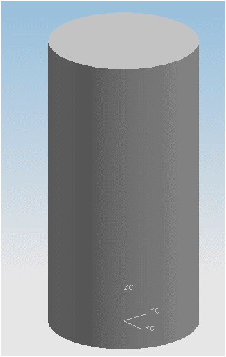
The screen will now look like the following figure.
Right-click on the screen and choose ORIENT VIEW → TRIMETRIC
> If the solid is in wire-frame, right-click on the screen and choose RENDERING STYLE → SHADED 
OR click on the Shaded icon in the toolbar 


Now you will be able to see a solid cylinder.
Now let us practice some Layer Commands.
> Choose FORMAT → MOVE TO LAYER


You will be asked to select a surface or solid.
> Move the cursor on to the cylinder and click on it so that it becomes highlighted.
> Click OK
You will get the following pop window.
> In the Destination Layer or Category space at the top of the window, type 61.
> Choose APPLY, then CANCEL


The Cylinder has now gone to the 61st layer. It can no longer be seen in Layer 1.
> To see the cylinder, click FORMAT → LAYER SETTINGS
> Double-click on 61 so that Selectable shows next to it
> Click OK


The cylinder will again be seen on the screen.

There is no cylinder in layer 1


Tuesday, 8 November 2011

Basics of UG

Mouse Controls:

Rotate:
> Press and hold the middle mouse button (or scroll button) and drag around the screen to view the model in the direction you want. The model can also be rotated about a single axis. To rotate about the axis horizontal to the screen, place the mouse pointer near the right edge of the graphic screen and rotate. Similarly, for the vertical axis and the axis perpendicular to the screen, click at the bottom edge and top edge of the screen respectively and rotate.
>If you keep pressing the MB2 at the same position for a couple of seconds, it will fix the point of rotation (a green + symbol appears) and you can drag around the object to view

Pan:
> Press and hold both the middle button and right mouse button simultaneously and drag OR
> Press and hold <Shift> button on the keyboard and press and drag the middle mouse button. 

Zoom In /Out:
> Press and hold both the left mouse button and middle button (or scroll button) simultaneously and drag OR > Press and hold <Ctrl> button on the keyboard and then press and drag the middle mouse button. OR
> Scroll up and down if the mouse has a scroll wheel


In short form:     
  •  Zoom – Ctrl + MB2
  •  Pan- Shift + MB2
  •  Rotate – MB2
  •  MB1 = Left button – Used for selection
  •  MB2 = Center button - Acceptance
  •  MB3 = Right button – Context sensitive menu

DEFINITION OF CAD/CAM/CAE

Computer Aided Design – CAD
CAD is technology concerned with using computer systems to assist in the creation,modification, analysis, and optimization of a design. Any computer program that embodies computer graphics and an application Program facilitating engineering functions in design process can be classified as CAD software.

The most basic role of CAD is to define the geometry of design – a mechanical part, a product assembly, an architectural structure, an electronic circuit, a building layout, etc. The greatest NX5 for Engineering Design 1 0 Missouri University of Science and Technology benefits of CAD systems are that they can save considerable time and reduce errors caused by otherwise having to redefine the geometry of the design from scratch every time it is needed.

Computer Aided Manufacturing – CAM
CAM technology involves computer systems that plan, manage, and control the manufacturing operations through computer interface with the plant’s production resources.One of the most important areas of CAM is numerical control (NC). This is the technique of using programmed instructions to control a machine tool, which cuts, mills, grinds, punches or turns raw stock into a finished part. Another significant CAM function is in the programming of robots. Process planning is also a target of computer automation.

Computer Aided Engineering – CAE
CAE technology uses a computer system to analyze the functions of a CAD-created product, allowing designers to simulate and study how the product will behave so that the design can be refined and optimized.

CAE tools are available for a number of different types of analyses. For example, kinematic analysis programs can be used to determine motion paths and linkage velocities in mechanisms.Dynamic analysis programs can be used to determine loads and displacements in complex assemblies such as automobiles. One of the most popular methods of analyses is using a Finite Element Method (FEM). This approach can be used to determine stress, deformation, heat transfer, magnetic field distribution, fluid flow, and other continuous field problems that are often too tough to solve with any other approach.

Related Posts Plugin for WordPress, Blogger...